fuse box diagrams (location, arrangement, functions, purpose) in the passenger compartment and engine compartment of the Acura TL (1999, 2000, 2001, 2002, 2003).
Checking and replacing fuses
If something electrical in your car stops working, the first thing you should check is a blown fuse. Use the chart or diagram on the fuse box cover to determine which fuse or fuses control that component. Check those fuses first, but check all fuses before deciding that a blown fuse is not the cause. Replace any blown fuses and test the component for operation.
- Turn the ignition key to the LOCK (0) position. Make sure the headlights and all other accessories are off.
- Remove the cover from the fuse box.
- Check each of the large fuses in the underhood fuse box by looking through the top to the wire inside.
- Check the smaller fuses in the underhood fuse box and all fuses in the interior fuse boxes by pulling each fuse with a fuse puller located in the underhood fuse box.
- Find the blown wire inside the fuse. If it is blown, replace it with a spare fuse of the same rating or lower.
If you cannot drive the car without fixing the problem and you do not have a spare fuse, get a fuse of the same or lower rating from one of the other circuits. Make sure you can temporarily bypass that circuit (such as an outlet or radio). If you replace a blown fuse with a lower-rated spare fuse, it may blow again. This does not indicate anything. Replace the fuse with a fuse of the correct rating as soon as possible. - If a replacement fuse of the same rating blows after a short time, your vehicle likely has a serious electrical problem. Leave the blown fuse in that circuit and have a qualified mechanic check your vehicle.
Note
Replacing a fuse with a higher rating greatly increases the chances of damaging the electrical system. If you do not have a spare fuse with the correct rating for the circuit, install a fuse with a lower rating.
Overview of the passenger cabin
Advertisements
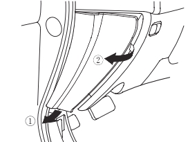
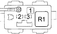
Fuse box diagram #1 in the passenger compartment.
The interior fuse boxes are located on each side of the instrument panel. To access the interior fuse box, open the vehicle door. Open the bottom of the cover, then pull it out of the side hinges.
| No. | A | Protected component |
|---|---|---|
| 1 | 15 | PGM-FI Main Relay, Supplemental Restraint System (SRS) Unit |
| 2 | 10 | Supplemental Restraint System (SRS) Unit |
| 3 | 7.5 | HVAC, Radiator Fan Control Module, Rear Window Defogger Relay, Fan Control Relay (Type S) |
| 4 | 7.5 | ABS-TCS control unit (except type S), heated power mirrors, power mirrors, auxiliary connector S, seat heater relay, VSA control unit (type S) |
| 5 | 7.5 | Daytime running lights (DRL) control unit |
| 6 | 15 | Charging System, Cruise Control, Electrical Load Detector (ELD) Unit, Engine Mounting Control System, Evaporative Emission Control System, PCM (VBSOL), Primary and Secondary Heated Oxygen Sensors (HO2S), Radiator Fan Control Module, VSP Sensor (1999 w/Navigation), Cruise Control/TCS Switch (except Type S) or Cruise Control/VSA Off Indicator (Type S), Intake Manifold Runner Control (IMRC) Module (Type S), VSA Control Unit (Type S) |
| 7 | 7.5 | Occupant Position Detection System (OPDS) Unit (2000-2002), Shift Lock Relay (1999), Wiper/Washer (1999) |
| 8 | 7.5 | Accessory Power Port Relay, Navigation System, Aux R Port, Shift Lock Solenoid |
| 9 | 7.5 | Auto Dimming Interior Mirror, Brake Light Malfunction Sensor, Clock (W/Nav), Driver & Passenger Multiplexer Control Units, Daytime Running Light (DRL) Indicator, Sensor Assembly, Reverse Relay, Shift Lock Relay (2000-2002) |
| 10 | 7.5 | Turn signal/hazard warning relay |
| 11 | 15 | Ignition coils |
| 12 | 30 | Wiper |
| 13 | 7.5 | Starter Signal, PGM-FI Main Relay, Powertrain Control Module (PCM) |
| Relay | ||
| R1 | Starting cut | |
| R2 | Ensure regression | |
| R3 | Direction indicator / Danger | |
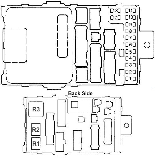
Fuse Box #2 in the Passenger Compartment Diagram
| No. | A | Protected component |
|---|---|---|
| 1 | 30 | 1999-2001: Hatch closing and opening relay |
| 20 | 2002-2003: Power Window Control Unit (Driver’s Power Window) | |
| 2 | 20 | 1999-2001: Driver’s power seat adjustment switch (reclining). |
| 20 | 2002-2003: Power Seat Control Unit (Reclining) | |
| 3 | 20 | Seat heating relay |
| 4 | 20 | 1999-2001: Driver’s power seat adjustment switch (sliding). |
| 20 | 2002-2003: Power Seat Control Unit (Slide) | |
| 5 | 20 | Front passenger power seat adjustment switch (sliding), passenger multiplexer control unit |
| 6 | 20 | Front passenger power seat adjustment switch (tilt) |
| 7 | 20 | Left Power Window Switch, Door Multiplexer Control Unit (2002-2003), Sunroof Close/Open Relay, Power Window Control Unit (2002-2003) |
| 8 | 20 | Front passenger window switch |
| 9 | 20 | Accessory Power Port Relay, Audio System, Front Accessory Power Port, Rear Accessory Power Port, Stereo Amplifier |
| 10 | 10 | Daytime Running Lights (DRL) Control Unit, Navigation Display Unit, Navigation Relay (’99), Navigation Unit |
| 11 | 7.5 | Ceiling light, Driver and front passenger door light, Passenger multiplex control unit, Trunk lid opener, Power seat control unit (2002-2003), Spotlights, Trunk light |
| 12 | 20 | Power door lock, passenger multiplex control unit, trunk lid master release |
| 13 | 7.5 | Climate Control Module, Clock (except Navigation), Driver, Door and Passenger Multiplexer Control Module, Driver Position Memory Switch (2002-2003), Sensor Assembly, Keyless Entry Receiver Module (2002-2003), PCM (VBU), Radiator Fan Control Module (2002-2003), Security Indicator |
| 14 | 7.5 | except type S: ABS-TCS control unit |
| 7.5 | Type S: Air Conditioning Compressor | |
| 15 | 20 | 1999-2001: Door multiplexer control unit (driver’s window) |
| 30 | 2002-2003: Hatch closing and opening relay | |
| 16 | 20 | Rear right window switch |
| Relay | ||
| R1 | Window lifter | |
| R2 | Accessory slot | |
| R3 | Rear window heating | |
Advertisements
Engine bay overview
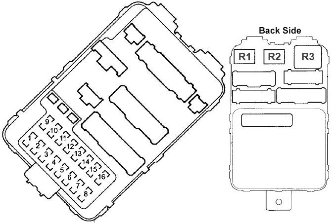
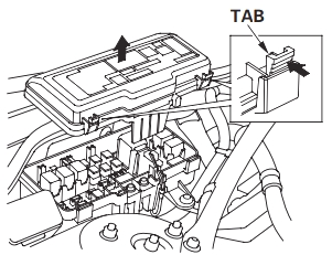
Engine Compartment Fuse Box Diagram
The underhood fuse box is located at the rear of the engine compartment on the passenger side. To open it, press the tabs.
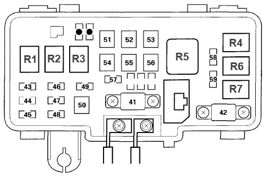
| No. | A | Protected component |
|---|---|---|
| 41 years old | 120 | Generator, Battery, Power Distribution |
| 42 | 60 | Ignition Switch (BAT) |
| 43 | 20 | Right headlight, daytime running lights (DRL) control unit |
| 44 | — | — |
| 45 | 20 | Left Headlight, Light Combination Switch (2002-2003), Daytime Running Light (DRL) Control Unit, DRL Diode, Sensor Assembly, High Beam (DRL) Cut-off Relay |
| 46 | 15 | Data Link Connector (DLC), PGM-FI Main Relay |
| 47 | 20 | Brake Pedal Position Switch, Horn Relay, Ignition Key/Key Light, Horn Relay (’99) |
| 48 | 20 | ABS Safety Relay (1999-2001), TCS Relay (except Type S) (2002-2003), VSA Relay (Type S) (2002-2003) |
| 49 | 15 | Hazard warning switch |
| 50 | 30 | 1999-2001: ABS Pump Motor Relay |
| 20 | Type S: VSA Throttle Relay | |
| 51 | 40 | Window lift motor, window lift relay |
| 52 | 20 | 1999-2001: TCS Fail Safe Relay |
| 20 | 2002-2003: Fog Light Relay | |
| 53 | 40 | Rear Window Defogger Relay |
| 54 | 40 | Fuse (Passenger Compartment Fuse Box No. 2): No. 9, 10, 11, 12, 13 |
| 55 | 40 | Fuse (Passenger Compartment Fuse Box No. 1): No. 2, 3, 4, 5, 6 |
| 56 | 40 | Fan Motor Relay |
| 57 | 20 | except type S: radiator fan relay |
| 30 | Type S: Radiator Fan Relay | |
| 58 | 20 | except type S: A/C compressor clutch relay, condenser fan relay, radiator fan control module (1999-2001) |
| 30 | Type S: A/C Compressor Clutch Relay, Condenser Fan Relay, Radiator Fan Control Module (1999-2001) | |
| 59 | 15 | Tail light relay |
| • | — | — |
| Relay | ||
| R1 | Headlight #1 | |
| R2 | Headlight #2 | |
| R3 | Horn | |
| R4 | Air conditioner condenser fan | |
| R5 | Fan motor | |
| R6 | Radiator fan | |
| R7 | Air conditioning compressor clutch | |
Relay box in the engine compartment
№1 (1999-2001)
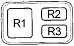
| No. | Relay |
|---|---|
| R1 | ABS pump motor |
| R2 | ABS/TCS failsafe |
| R3 | TCS |
№2
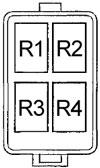
| No. | Relay |
|---|---|
| R1 | Shift Lock |
| R2 | 2002-2003: Tail light |
| R3 | 2002-2003: Heated seats |
| 1999-2001: Safety Signal | |
| R4 | 2002-2003: High beam relay (daytime running lights) |
| 1999-2001: Heated seats. |
№3 (2002-2003)
| No. | A | Protected component |
|---|---|---|
| 1 | 40 | Engine with ABS |
| 2 | 20 | ABS F/S |
| 3 | 7.5 | Checking the ABS Engine |
| Relay | ||
| R1 | ABS pump motor | |